FOCUSES ON PLASTIC INJECTION AND MOLD DESIGN.
DONGGUAN LONGKE ELECTRONIC TECHNOLOGY CO., LTD.
Focus on R & D, production and marketing of precision connectors, electronic connecting lines, metal stamping, mold design
Enterprise mailbox
sales@longke-china.com
NEWS
FOCUSED ON CONNECTOR
主页 > Home > News > Common problem >
Common problem
What are the production processes of electronic connectors?
- Release date:19-10-23 09:26
- Clicks:173
There are many kinds of electronic connectors, but the manufacturing process can be basically divided into the following four stages:
Stamping
Plating
Molding
Assembly
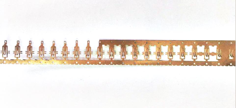
1. stamping
The manufacturing process of electronic connector generally starts from stamping pin. Through the large-scale high-speed stamping machine, the electronic connector (PIN) is made of thin metal strip. One end of the large coil metal belt is fed into the front end of the press, the other end passes through the hydraulic workbench of the press and wraps into the winding pulley, which pulls out the metal belt and rolls it to punch the finished product.
2. electroplating
The connector pins shall be sent to the electroplating section after stamping. At this stage, the electronic contact surface of the connector will be coated with various metal coatings. A kind of problems similar to stamping stage, such as the twist, fragmentation or deformation of pins, will also appear in the process of stamping pins into electroplating equipment. Through the technology described in this paper, such quality defects are easy to be detected.
However, for most machine vision system suppliers, many quality defects in the plating process are also "forbidden areas" of the inspection system. Electronic connector manufacturers hope that the detection system can detect various inconsistent defects such as small scratches and pinholes on the electroplated surface of connector pins. Although these defects are easy to be identified for other products (such as aluminum can bottom cover or other relatively flat surface), due to the irregular and angular surface design of most electronic connectors, it is difficult for the visual inspection system to get enough images to identify these minor defects.
Because some types of pins need to be plated with multiple layers of metal, manufacturers also want the detection system to be able to distinguish various metal coatings in order to check whether they are in place and in the right proportion. This is a very difficult task for a vision system using a black-and-white camera, because the gray levels of images with different metal coatings are virtually the same. Although the camera of color vision system can successfully distinguish these different metal coatings, the problem of lighting difficulty still exists due to the irregular angle and reflection of the coating surface.
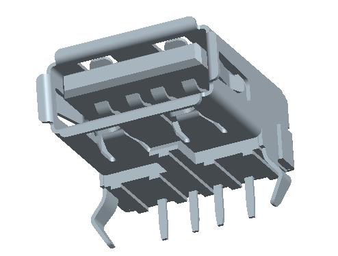
3. injection molding
The plastic box seat of the electronic connector is made in the injection molding stage. The usual process is to inject the melted plastic into the metal mould and then cool it quickly. When the melted plastic fails to completely fill the fetal film, the so-called "leakage" (short shorts) appears, which is a typical defect to be detected in the injection stage. Other defects include a full or partially blocked Jack (these jacks must be kept clean and unobstructed so that they can be properly plugged into the pins during final assembly). The machine vision system for quality inspection after injection molding is relatively simple and easy because the backlight can easily identify the leakage of box seat and plug of connector.
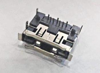
4. assembly
The final stage of electronic connector manufacturing is finished product assembly. There are two ways to connect the electroplated pins with the injection box seat: single or combined. Single docking refers to inserting one pin at a time; combined docking refers to inserting multiple pins with the box seat at the same time. No matter which plug-in method is adopted, the manufacturer requires to check whether all pins are missing and correctly positioned in the assembly stage; another kind of routine testing task is related to the measurement of the spacing on the connector mating surface.
As in the stamping stage, the assembly of connector also challenges the automatic detection system in the detection speed. Although most assembly lines have a beat of one or two per second, the visual system usually needs to complete several different inspection projects for each connector passing through the camera. So the detection speed becomes an important system performance index again.
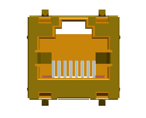
After assembly, the overall dimension of the connector is much larger than the allowable dimension tolerance of a single pin in order of magnitude. This also brings another problem to the vision detection system. For example, if the size of some connector box seats exceeds one foot and there are hundreds of pins, the detection accuracy of each pin position must be within the dimension range of several thousandths of an inch. Obviously, it is impossible to detect a foot long connector on an image, and the visual detection system can only detect a limited number of pin quality in a small field of vision at a time. In order to complete the detection of the whole connector, there are two ways: using multiple cameras (increasing the system cost); or when the connector passes in front of a lens, continuously triggering the camera, the vision system will "sew" the single frame images taken continuously to judge whether the whole connector is qualified. The latter method is commonly used by ppt visual inspection system after the connector is assembled.
The detection of "true position" is another requirement of connector assembly for detection system. This "actual position" refers to the distance between the top of each pin and a specified design reference line. The visual inspection system must make this imaginary baseline on the inspection image to measure the "actual position" of each pin vertex and judge whether it meets the quality standard. However, the reference point used to draw the reference line is often invisible on the actual connector, or sometimes appears on another plane and cannot be seen at the same time of the same lens. Even in some cases, the plastic on the connector box has to be removed to determine the position of the reference line. A related topic, design for detectability, does appear here.
Inspectability design
Due to the continuous requirements of manufacturers for improving production efficiency and product quality and reducing production costs, new machines
Stamping
Plating
Molding
Assembly
1. stamping
The manufacturing process of electronic connector generally starts from stamping pin. Through the large-scale high-speed stamping machine, the electronic connector (PIN) is made of thin metal strip. One end of the large coil metal belt is fed into the front end of the press, the other end passes through the hydraulic workbench of the press and wraps into the winding pulley, which pulls out the metal belt and rolls it to punch the finished product.
2. electroplating
The connector pins shall be sent to the electroplating section after stamping. At this stage, the electronic contact surface of the connector will be coated with various metal coatings. A kind of problems similar to stamping stage, such as the twist, fragmentation or deformation of pins, will also appear in the process of stamping pins into electroplating equipment. Through the technology described in this paper, such quality defects are easy to be detected.
However, for most machine vision system suppliers, many quality defects in the plating process are also "forbidden areas" of the inspection system. Electronic connector manufacturers hope that the detection system can detect various inconsistent defects such as small scratches and pinholes on the electroplated surface of connector pins. Although these defects are easy to be identified for other products (such as aluminum can bottom cover or other relatively flat surface), due to the irregular and angular surface design of most electronic connectors, it is difficult for the visual inspection system to get enough images to identify these minor defects.
Because some types of pins need to be plated with multiple layers of metal, manufacturers also want the detection system to be able to distinguish various metal coatings in order to check whether they are in place and in the right proportion. This is a very difficult task for a vision system using a black-and-white camera, because the gray levels of images with different metal coatings are virtually the same. Although the camera of color vision system can successfully distinguish these different metal coatings, the problem of lighting difficulty still exists due to the irregular angle and reflection of the coating surface.
3. injection molding
The plastic box seat of the electronic connector is made in the injection molding stage. The usual process is to inject the melted plastic into the metal mould and then cool it quickly. When the melted plastic fails to completely fill the fetal film, the so-called "leakage" (short shorts) appears, which is a typical defect to be detected in the injection stage. Other defects include a full or partially blocked Jack (these jacks must be kept clean and unobstructed so that they can be properly plugged into the pins during final assembly). The machine vision system for quality inspection after injection molding is relatively simple and easy because the backlight can easily identify the leakage of box seat and plug of connector.
4. assembly
The final stage of electronic connector manufacturing is finished product assembly. There are two ways to connect the electroplated pins with the injection box seat: single or combined. Single docking refers to inserting one pin at a time; combined docking refers to inserting multiple pins with the box seat at the same time. No matter which plug-in method is adopted, the manufacturer requires to check whether all pins are missing and correctly positioned in the assembly stage; another kind of routine testing task is related to the measurement of the spacing on the connector mating surface.
As in the stamping stage, the assembly of connector also challenges the automatic detection system in the detection speed. Although most assembly lines have a beat of one or two per second, the visual system usually needs to complete several different inspection projects for each connector passing through the camera. So the detection speed becomes an important system performance index again.
After assembly, the overall dimension of the connector is much larger than the allowable dimension tolerance of a single pin in order of magnitude. This also brings another problem to the vision detection system. For example, if the size of some connector box seats exceeds one foot and there are hundreds of pins, the detection accuracy of each pin position must be within the dimension range of several thousandths of an inch. Obviously, it is impossible to detect a foot long connector on an image, and the visual detection system can only detect a limited number of pin quality in a small field of vision at a time. In order to complete the detection of the whole connector, there are two ways: using multiple cameras (increasing the system cost); or when the connector passes in front of a lens, continuously triggering the camera, the vision system will "sew" the single frame images taken continuously to judge whether the whole connector is qualified. The latter method is commonly used by ppt visual inspection system after the connector is assembled.
The detection of "true position" is another requirement of connector assembly for detection system. This "actual position" refers to the distance between the top of each pin and a specified design reference line. The visual inspection system must make this imaginary baseline on the inspection image to measure the "actual position" of each pin vertex and judge whether it meets the quality standard. However, the reference point used to draw the reference line is often invisible on the actual connector, or sometimes appears on another plane and cannot be seen at the same time of the same lens. Even in some cases, the plastic on the connector box has to be removed to determine the position of the reference line. A related topic, design for detectability, does appear here.
Inspectability design
Due to the continuous requirements of manufacturers for improving production efficiency and product quality and reducing production costs, new machines
- 【Printing】
- 【Collection】
- 【Return】
相关产品RELATED PRODUCTS
Address: No.28, southwest Lang Road, Henan Industrial Zone, Jinxia, Chang'an Town, Dongguan City, Guangdong Province